
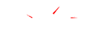


In the third and final part of our forced induction series, we’re looking at turbochargers. Turbos are becoming ever more common on cars in the quest for efficiency and better emissions. Without further ado let’s get into it.
Turbos are essentially exhaust gas driven superchargers. Take for instance the centrifugal supercharger we looked at in the previous article. Rather than a belt spinning the compressor wheel, the turbo has an turbine in the exhaust housing that is spun by exhaust gases. This turbine is connected by a shaft to the compressor wheel. Once at full boost turbos can spin up to 150 000rpms!

Journal vs Ball Bearing Turbochargers
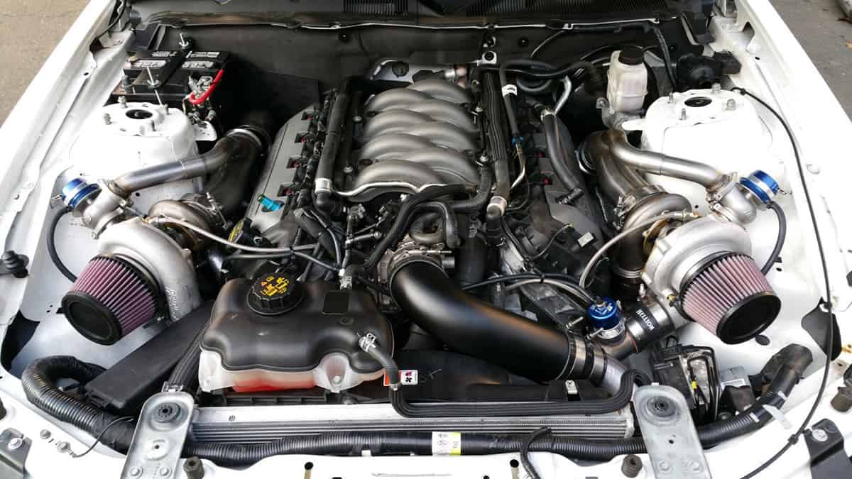
To be able to handle such high rotational speeds, turbos have special bearings to support the shaft between the two wheels. It is also very important that the entire rotating assembly is properly balanced so as not to destroy itself at those speeds.
Older turbos have Journal bearings, where the shaft is suspended in oil. This has a secondary function of cooling the turbo as well.
Newer turbos use Ball bearings, which as the name suggests use oil lubricated ball bearings. They are the more durable option, though a bit more expensive than a journal bearing turbo. Both turbos are capable of producing the same power however a ball bearing turbo will spool faster and provide a slightly different driving experience to a journal bearing turbo.

Turbocharger Wheels
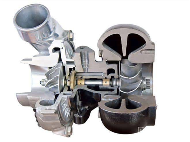
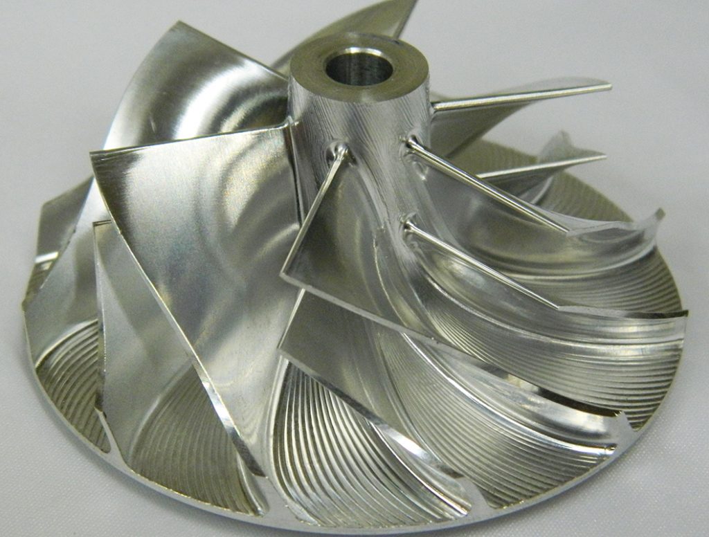
Turbocharger wheels need to be light to allow them to spin quickly and easily at high speeds. Initially turbocharger wheels were made from ceramic materials. This allowed them to spool up quickly and handle high temperatures. The downside is that when pushed beyond the manufacturer designed boost levels, they tend to shatter.
Manufacturers moved to cast aluminium alloys in the 1990’s but other alloys have been introduced as well to off the best durability. These include magnesium and stainless steel alloys. However the majority of standard wheels are still aluminium alloys.
The latest process is Machined From Solid (MFS) also called Billet wheels. In this process, turbocharger wheels are milled from a solid piece of forged aluminium. This allows the wheels to be lightweight, but also much stronger than cast units.
Twin Scroll & Variable Geometry Turbos
These are two new technologies that try to improve the range of a turbocharger. Normally a small turbocharger will spool up quickly but will become too much of a restriction at high rpms to continue creating power. Conversely a larger turbocharger will have a lot of lag in low rpms but create a lot of top end power. Variable geometry and twin scroll turbos try to get around both of these limitations in different ways.

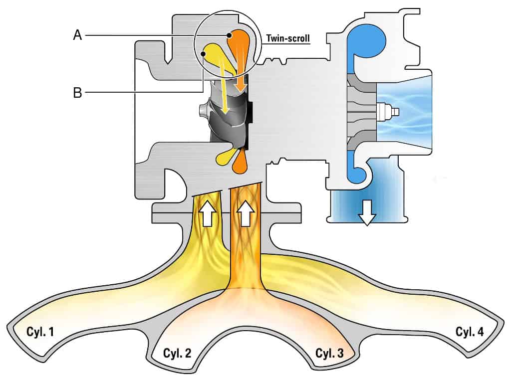
Twin Scroll Turbo: A twin scroll turbo will split the exhaust gases to feed two different scrolls within the turbine housing. For instance, this allows an inline 4 cylinder to make the most of cylinder overlap and maintain maximum efficiency when spooling up the turbo.

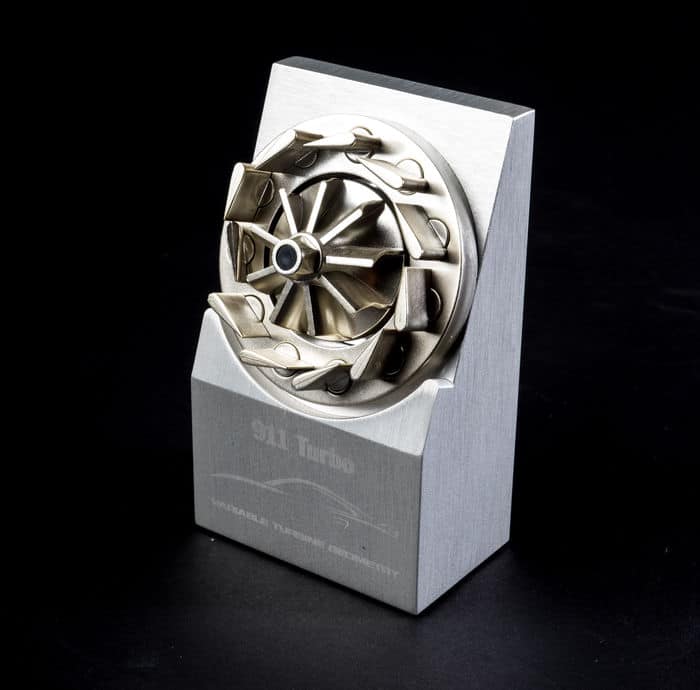
Variable Geometry Turbos: These types of turbos are more common on diesel engines that have lower exhaust temperatures. Their use on petrol vehicles is limited because of the expensive, exotic materials needed to make them work. A VGT is basically a larger turbocharger that has variable vanes in the exhaust housing that move to change the internal ratios to make it behave like a smaller turbo. This allows the turbo to have a very good spool at low rpm and good capacity at high rpms.
Internal vs External Wastegates
A wastegate diverts exhaust gases away from the turbine wheel. A diaphragm with a boost reference port opens or closes the the wastegate to control the amount of boost produced. Functionally an internal & external wastegate perform the same function but external wastegates can offer better performance.

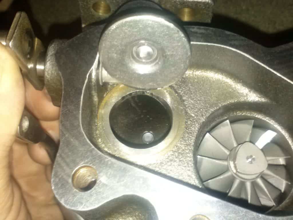
Internal Wastegate
As the name suggests, an internal wastegate is built into the exhaust housing of the turbo and diverts exhaust gases around the turbine wheel. Once the turbo has reached its set boost level the wastegate will open allowing the turbo to maintain the required boost. Internal wastegates, are compact, simple and allow the exhaust gases to travel seamlessly into the exhaust. This is the system used on virtually all OEM turbos.

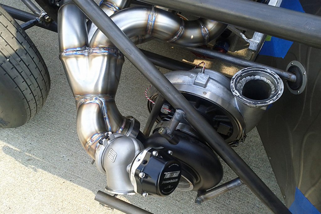
External Wastgate
These are completely separate units to the actual turbocharger and are often used in high horsepower builds. External wasgates give better control of the exhaust gases and when plumbed back into the exhaust, better flow characteristics than an internal wastegate. When the external wastegate is not plumbed back into the exhaust it is known as a screamer pipe for its loud noise (often accompanied by flames).
Boost Controllers
Boost controllers fall into two general categories, manual and electronic. These boost control units determine how much boost is “seen” by the wastegate actuator. This will determine how quickly boost comes on and how aggressively it is produced.

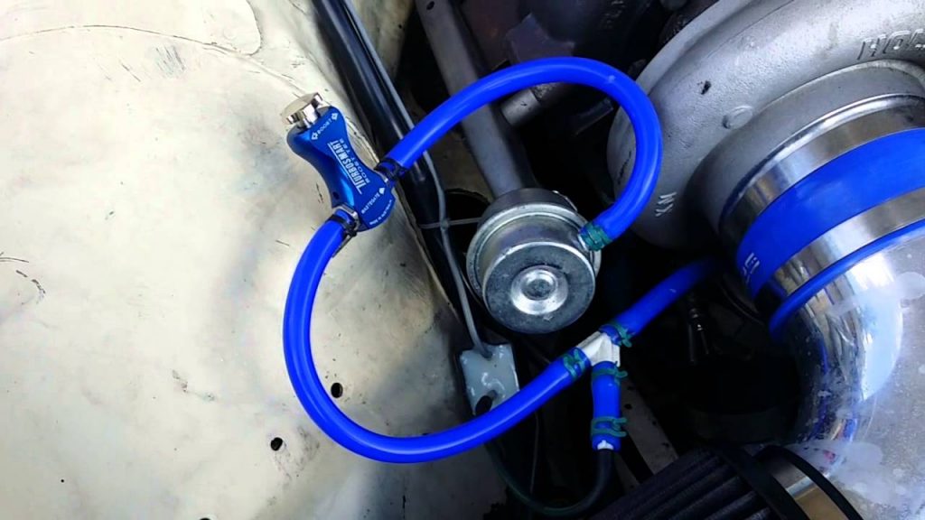
Manual boost controllers are largely just controlled boost leaks. They bleed off the boost reference in a controlled manner to allow the wastegate to remain closed longer. As an aftermarket addition they allow the user to increase the boost on their OEM turbo easily and cost effectively. Boost will come on slightly faster than stock.


Electronic boost controllers can either be separate aftermarket units or be a function of an aftermarket ECU. Electronic boost controllers allow for infinite tuning to make the most out of the turbo. From how quickly the turbo spools, to how aggressively the boost comes on. Some units can even have variable boost-by-gear to allow the best compromise of boost and traction.
BiTurbo vs Twinturbo
This is nothing more than a marketing choice; they are the same thing. Twin turbo systems first came into use as a way to minimise the lag created by a large single turbo. There are however different types of twin turbo systems which we will explore below.

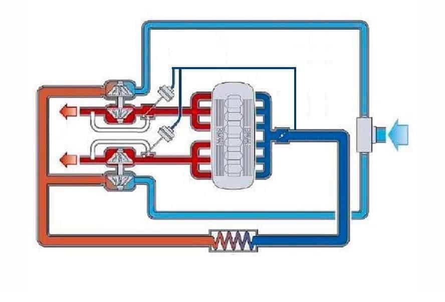
Parallel Twin Turbos
This setup consists of two same sized turbos, each being spooled by half of the engine. Parallel setups is typically used on V-engines but also on inline 6 cylinder engines such as the BMW N54 and Nissan’s RB26DETT. This allows the engine to have quick response from low down in the rpms. Manufacturers like BMW and Mercedes have begun to use hot V’s to further shorten piping to improve performance.

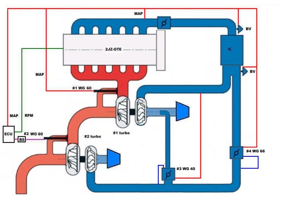
Sequential Twin Turbos
This setup consists of small turbo for low rpms and a larger turbo for higher rpms. The sequential turbo system was designed to offer the best of both worlds, quick response and unrelenting top end power.The downsides of this system however was the complex piping and in some cases, a drop off in boost during the changeover. In the Subaru world, this is known as the Valley of Death. Subaru’s B4 Legacy and Mazda’s Rx7 are two notable examples of sequential turbo setups.
Hopefully this primer has shed some light on the world of turbos. There is constant development in producing more efficient, better spooling turbos as the world moves to more environmentally responsible motoring and performance.
Mr Tate once again big thanks for that piece.We are learning ey. It’s so informative and hope you continue to publish work like this. The wording is perfect and easier to understand.Appreciate it